555 Timer Circuit Schematic / 555 Timer Draws Zero Off Current Edn - Tone generators have a number of uses in electronics.
byAdmin-
0
555 Timer Circuit Schematic / 555 Timer Draws Zero Off Current Edn - Tone generators have a number of uses in electronics.. You can either follow the previous schematic or follow the breadboard wiring diagram below. Clap switch circuit using ic 555 timer & without timer. Each component has the schematic symbol and a label printed on. The circuit layout is for a 555 timer in astable mode. The 555 can be used to derivatives provide two (556) or four (558) timing circuits in one package.2.
555 timer was first introduced by signetics corporation in 1971 as se555/ne555. To make the same circuit as mentioned above without ic 555 timer, we will have to use the following basic electronic components and devices. Clap switch circuit using ic 555 timer & without timer. You can either follow the previous schematic or follow the breadboard wiring diagram below. The circuits explained here are 10 best small timer circuits using the versatile chip ic 555, which generates predetermined time intervals in response the image shown below represents the internal schematic of a standard ic 555.
File Pwm Using 555 Timer Circuit Diagram Webp Wikipedia from upload.wikimedia.org The standard 555 timer ic is used in a variety of timer, pulse generation and oscillator applications. The ne555, sa555, and se555 monolithic timing circuits are highly stable controllers capable of producing accurate time delays or oscillation. You can watch the following video or read the written tutorial below. Above schematic diagram shows the 555 timer monostable multivibrator circuit. The 555 and 7555 are called timers or timer chips. This bistable configuration does not use any rc timing. And now a full schematic of the 555 timer oscillator with single step and free run option. A better circuit is using a 555 timer.
The timer generates an output pulse with an on time period determined by the rc network i.e t = 1.1rc.
Learn about the 555 timer and how it works in astable mode. You can explore various applications based on monostable. Connect power and ground to pins 8 and 1 of the 555 timer (red and black wires). Look at the circuit diagram. Print the diagram in the centre of a sheet of paper create a circuit using the ics pin locations. It is a affordable, stable and user friendly ic in application such as monostable and bi stable. And now a full schematic of the 555 timer oscillator with single step and free run option. In this case, the fixed value of the capacitor is 100uf. The lm555 has a maximum typical supply voltage rating of 16v while the relay's armature coil is enabled at 12v. With this information you will learn how how the 555 works and will have the experience to build some of the circuits below. Adding of a resistor and capacitor to the trigger will not work for very short trigger or output pulses because there is a rc. This tutorial provides sample circuits to set up a 555 timer in monostable, astable, and bistable modes as well as an in depth discussion of wiring info: The 555 timer can provide time delays ranging from several minutes for one cycle of operation to many thousands of cycles per second.
Finally, power up your circuit by connecting the battery to your breadboard In this tutorial we will learn how the 555 timer works, one of the most popular and widely used ics of all time. Look at the circuit diagram. Basically, this means that you will have a continuous transition from a high voltage level (determined by and slightly less than your supply voltage) to 0v at a certain frequency (number of times per second). The red section is the.
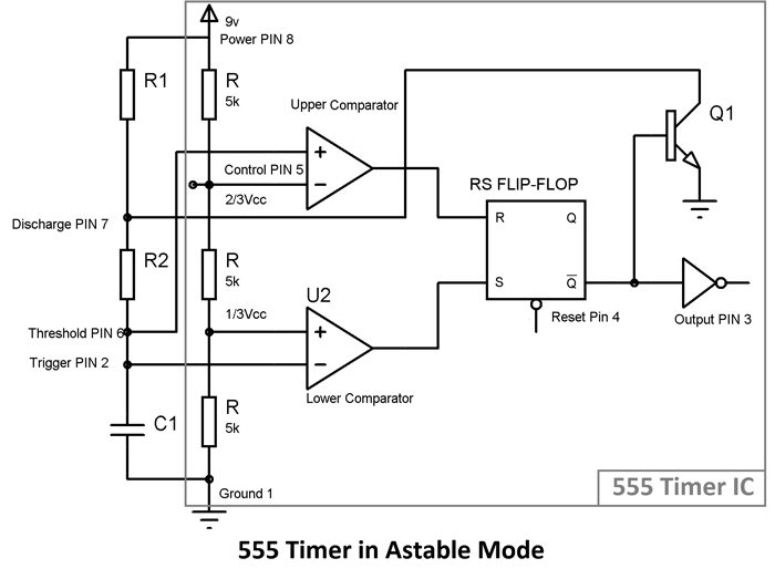
555 Timer Astable Multivibrator Circuit Diagram from circuitdigest.com Introduced in 19723 by signetics,4 the 555 is still in widespread use. Finally, power up your circuit by connecting the battery to your breadboard The lm555 has a maximum typical supply voltage rating of 16v while the relay's armature coil is enabled at 12v. Connect power and ground to pins 8 and 1 of the 555 timer (red and black wires). Lm555 timer internal circuit block diagram. We can see that it us made up of 21 transistors, 4 diodes, and 15. Typical schematics in monostable operation. 555 timer ic remains in stable state until the external triggering is applied.
Basically, this means that you will have a continuous transition from a high voltage level (determined by and slightly less than your supply voltage) to 0v at a certain frequency (number of times per second).
And now a full schematic of the 555 timer oscillator with single step and free run option. The timer generates an output pulse with an on time period determined by the rc network i.e t = 1.1rc. Derivatives provide two (556) or four (558) timing circuits in one package. A better circuit is using a 555 timer. Each component has the schematic symbol and a label printed on. The schematic is shown in fig 5. The 555 timer is a simple integrated circuit that can be used to make many different electronic circuits. The 555 timer is an integrated circuit, it is extremely versatile and can be used to build lots of different circuits. You can explore various applications based on monostable. The 555 timer ic is an integrated circuit (chip) used in a variety of timer, delay, pulse generation, and oscillator applications. You can either follow the previous schematic or follow the breadboard wiring diagram below. With this information you will learn how how the 555 works and will have the experience to build some of the circuits below. You can watch the following video or read the written tutorial below.
Each component has the schematic symbol and a label printed on. Finally, power up your circuit by connecting the battery to your breadboard The good thing is that this chip could work directly with 12v so no driver for the mosfet is needed. Typical schematics in monostable operation. The breadboard schematic of the above circuit is shown below.
1 To 15 Minute Timer Circuit Diagram Working And Applications from www.electricaltechnology.org Tone generators have a number of uses in electronics. Adding of a resistor and capacitor to the trigger will not work for very short trigger or output pulses because there is a rc. 555 timer ic remains in stable state until the external triggering is applied. Learn about the 555 timer and how it works in astable mode. The 555 timer is a simple integrated circuit that can be used to make many different electronic circuits. The 555 timer ic is an integrated circuit (chip) used in a variety of timer, delay, pulse generation, and oscillator applications. The 555 timer can provide time delays ranging from several minutes for one cycle of operation to many thousands of cycles per second. It's a simple source of oscillating in the schematic above, notice that the threshold pin and the trigger pin are connected to c1.
Introduced in 19723 by signetics,4 the 555 is still in widespread use.
Clap switch circuit using ic 555 timer & without timer. The circuit layout is for a 555 timer in astable mode. Connect power and ground to pins 8 and 1 of the 555 timer (red and black wires). This is the schematic below for the 555 timer that creates one square wave output. The 555 timer ic is an integrated circuit (chip) used in a variety of timer, delay, pulse generation, and oscillator applications. The jfet is a curious device that works well for the application provided we allow for the vgs(off) parameter. Derivatives provide two (556) or four (558) timing circuits in one package. Print the diagram in the centre of a sheet of paper create a circuit using the ics pin locations. 555 timer was first introduced by signetics corporation in 1971 as se555/ne555. 7 below, you'll see the circuit schematic of the 555 and the parts relevant to it. To observe the 555 timer in astable mode, let's build a circuit that uses the 555 timer's oscillating output to make. A 555 timer is a very versatile. Introduced in 19723 by signetics,4 the 555 is still in widespread use.